Introduction: Why Unity + LiDAR Is Becoming the Industry Standard
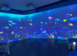
In recent years, interactive LiDAR systems have become a core technology in immersive experiences such as theme parks, museums, digital exhibitions, smart retail, and projection-based interactive installations.
Unity, as one of the most widely used real-time 3D engines, has become the preferred development platform for integrating LiDAR sensor data into interactive applications.
By combining LiDAR sensing technology with Unity’s rendering engine, developers can build:
- Interactive projection walls
- Motion-based game systems
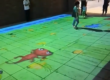
- Multi-user interactive floors
- Real-time tracking environments
- Smart spatial computing applications
However, integrating LiDAR with Unity is not a simple plug-and-play process. It requires careful system architecture design, data handling optimization, and real-time performance tuning.
This guide explains the full technical workflow from hardware setup to Unity integration, optimization, and deployment.
1. Understanding the Role of LiDAR in Unity Systems
Before integration, developers must understand what LiDAR actually provides.
A LiDAR sensor outputs:
- Distance measurements
- Point cloud data (X, Y, Z coordinates)
- Object boundaries
- Motion tracking information
- Real-time spatial mapping data
Unlike cameras, LiDAR does NOT rely on lighting conditions or image processing. Instead, it measures physical distance using laser pulses, making it ideal for:
- Low-light environments
- High-traffic interactive spaces
- Precision motion tracking systems
2. System Architecture Overview
A typical Unity + LiDAR system consists of four layers:
2.1 Hardware Layer
- LiDAR Sensor (360° or single-line)
- PoE switch or Ethernet connection
- Mounting structure (ceiling/wall)
2.2 Edge Computing Layer
- Industrial PC or mini PC
- Data preprocessing engine
- Filtering and clustering algorithms
2.3 Network Layer
- UDP/TCP communication
- Ethernet (preferred)
- Low-latency packet transmission
2.4 Unity Application Layer
- Real-time rendering engine
- Interaction logic system
- Visual effects and game logic
3. Hardware Setup for LiDAR + Unity Integration
3.1 Recommended Hardware Configuration
For stable performance:
- LiDAR Sensor: 10–30 FPS real-time scanning
- Network: Gigabit Ethernet (PoE preferred)
- Processing Unit: Intel i5/i7 or industrial ARM system
- RAM: Minimum 8–16GB
- GPU: Dedicated GPU recommended for heavy scenes
3.2 Installation Positioning
Proper sensor placement is critical:
- Ceiling mount for full-area coverage
- 2.5–4 meters height recommended
- Avoid reflective surfaces
- Ensure unobstructed scanning field
4. LiDAR Data Transmission to Unity
4.1 Communication Protocols
UDP (Recommended)
- Low latency
- Suitable for real-time interaction
- Minor packet loss acceptable
TCP
- More stable
- Higher latency
- Used for configuration data
Serial/Ethernet streaming
- Depends on sensor model
4.2 Data Format Structure
Typical LiDAR data includes:
- Timestamp
- X, Y, Z coordinates
- Intensity values
- Object ID (optional)
- Frame index
Example JSON structure:
{
  "timestamp": 1720000000,
  "points": [
    {"x": 1.2, "y": 0.5, "z": 2.1},
    {"x": 1.3, "y": 0.6, "z": 2.0}
  ]
}
5. Unity Project Setup
5.1 Scene Configuration
Create a base Unity scene:
- Set coordinate system (important for LiDAR alignment)
- Define interaction zones
- Create object layers for interaction
- Set frame update system
5.2 Required Unity Components
- Input Manager (LiDAR data receiver)
- Data Parser Module
- Interaction Controller
- Rendering Engine
- Event System
6. LiDAR Data Processing Pipeline in Unity
6.1 Data Reception Layer
Unity receives LiDAR data via:
- UDP socket listener
- Threaded background receiver
- Buffer queue system
6.2 Point Cloud Processing
Raw data must be processed before use:
Step 1: Noise Filtering
Remove random points caused by reflection errors.
Step 2: Clustering
Group points into human or object clusters.
Step 3: Tracking
Assign IDs to moving objects.
Step 4: Smoothing
Apply Kalman filter or exponential smoothing.
6.3 Coordinate Transformation
Convert LiDAR coordinates into Unity world space:
- Axis correction (Y-up vs Z-forward)
- Scaling factor adjustment
- Offset calibration
Formula example:
UnityX = LiDARX * scale
UnityY = LiDARY * scale
UnityZ = LiDARZ * scale
7. Real-Time Interaction System Design
7.1 Interaction Types
Interactive Walls
- Touchless UI activation
- Motion-triggered animations
Interactive Floors
- Step detection
- Area-based triggers
Multi-User Interaction
- Multiple object tracking
- Collision separation logic
7.2 Event System Design
Unity event structure:
- OnEnterZone()
- OnExitZone()
- OnHover()
- OnTriggerMotion()
8. Performance Optimization (Critical Section)
8.1 Reduce Latency
- Use UDP instead of TCP
- Reduce point cloud density
- Enable edge computing preprocessing
8.2 Optimize Unity Rendering
- Use object pooling
- Reduce Update() usage
- Use GPU instancing
- Disable unnecessary shadows
8.3 Memory Optimization
- Pre-allocate buffers
- Avoid runtime allocation in Update loop
- Reuse data arrays
8.4 Multi-Thread Architecture
Recommended structure:
- Thread 1: Data reception
- Thread 2: Data processing
- Thread 3: Unity rendering
9. Multi-Sensor Synchronization (Advanced)
For large installations:
- Synchronize timestamps
- Merge point clouds
- Handle overlap zones
- Calibrate field boundaries
10. Debugging and Calibration
10.1 Calibration Steps
- Sensor alignment
- Floor mapping
- Interaction zone definition
- Test object tracking
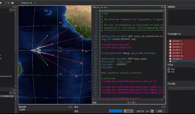
10.2 Debug Tools
- Real-time point cloud viewer
- FPS monitoring tool
- Latency measurement tool
11. Common Problems and Solutions
Problem 1: High latency
Solution: Reduce processing load + use UDP
Problem 2: Wrong coordinate mapping
Solution: Check axis transformation
Problem 3: Missing tracking objects
Solution: Improve clustering thresholds
Problem 4: Frame drops in Unity
Solution: Optimize rendering pipeline
12. Industry Applications
Theme Parks
- Interactive games
- Motion-triggered storytelling
Museums
- Educational interaction systems
- Digital exhibits
Retail
- Customer behavior tracking
- Interactive advertising walls
Smart Buildings
- Occupancy detection
- Space utilization analytics
13. Advanced Integration Options
- Unity + AI motion prediction
- LiDAR + camera fusion systems
- Cloud analytics integration
- XR/VR extension support
- Multi-room tracking systems
14. Why Use CPJROBOT PoE LiDAR for Unity Integration
CPJROBOT designs PoE-based interactive LiDAR systems specifically optimized for real-time applications.
Key advantages:
- Low-latency PoE architecture
- Real-time 360° scanning
- Stable SDK for Unity developers
- Industrial-grade reliability
- Optimized for interactive projection systems
- Easy integration with game engines
Conclusion
Integrating LiDAR sensors with Unity enables the creation of highly immersive, real-time interactive systems. However, success depends on a complete system-level approach including:
- Hardware selection
- Network architecture
- Data processing optimization
- Unity performance tuning
When properly implemented, Unity + LiDAR systems can achieve smooth, natural, and highly responsive interactive experiences suitable for commercial applications such as theme parks, museums, retail environments, and digital installations.
Looking to build a high-performance interactive system using LiDAR + Unity?
CPJROBOT is a professional PoE LiDAR manufacturer specializing in interactive sensing solutions for global developers and system integrators.