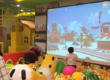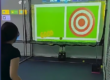

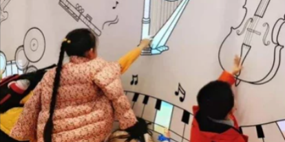
Interactive projection walls are transforming museums, science centers, corporate showrooms, and children’s entertainment spaces into engaging digital environments. Visitors can touch projected objects, activate animations, explore educational content, and interact with visual effects in real time.
However, creating a reliable interactive wall requires more than installing a projector and a LiDAR sensor.
For exhibition system integrators, common installation challenges include inaccurate touch positions, unexpected interaction points, detection blind spots, and inconsistent performance between multiple sensors.
How does a LiDAR interactive wall work, and how can these problems be prevented during installation?
This technical guide explains the operating principles of LiDAR interactive projection, practical calibration procedures, multi-LiDAR configurations, and troubleshooting methods for exhibition projects.
It also introduces how CPJROBOT PoE LiDAR sensors can support interactive wall installations through Ethernet connectivity, multi-touch detection, calibration software, and developer integration interfaces.
1. How Does a LiDAR Interactive Wall Work?
A LiDAR interactive wall combines laser distance measurement, coordinate processing, interactive software, and digital projection to create a touch-responsive display.
Unlike a conventional touchscreen, a LiDAR-based system can detect interactions near a projected surface without requiring a transparent touch panel across the entire wall.
1.1 LiDAR Scanning and Touch Detection
LiDAR stands for Light Detection and Ranging.
A 2D LiDAR sensor emits laser light and measures reflected signals to calculate distances to objects within its scanning plane.
For wall interaction, the sensor is positioned so its scanning plane covers the intended interaction region near the wall surface.
When a visitor’s finger or hand intersects this plane, the system can detect a change in the measured distance.
The processing software then determines whether the detected object represents a valid interaction.
The basic process is:
LiDAR Scanning → Object Detection → Coordinate Calculation → Touch Event → Animation Response
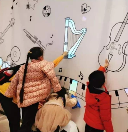
For example, in an interactive magic wall installation, a child touches a projected butterfly. The sensor detects the interaction position, and the application triggers an animation of the butterfly flying away.
Sound effects can also be activated by the interactive content software.
Importantly, the LiDAR detects positions within its scanning plane. It does not independently recognize every gesture, identify visual objects, or generate animations.
These functions depend on the software and overall system design.
1.2 How TUIO Connects LiDAR with Interactive Software
After detecting an interaction, the system must communicate its position to the interactive application.
One commonly used interface is TUIO (Tangible User Interface Object), a protocol designed for transmitting multi-touch and object-tracking information.
In a compatible CPJROBOT installation, the workflow may include:
- The LiDAR scans the interaction area.
- LiDAR Touch software processes the detected points.
- Calibration maps physical positions to application coordinates.
- Touch information is transmitted through a supported interface, such as TUIO.
- Unity, TouchDesigner, or another compatible application receives the events.
- The application generates visual and audio feedback.
TUIO is particularly useful when developing customized interactive exhibits because it separates the sensor detection process from the visual content engine.
For more technical information, read our guide on integrating LiDAR data with Unity using TUIO.
2. Why Is LiDAR Interactive Wall Calibration Important?
One of the most common problems during interactive wall installation is inaccurate touch positioning.
A visitor touches an object on the left side of the wall, but the animation appears several centimeters away.
This usually indicates a mismatch between the LiDAR coordinate system and the projected image.
2.1 Understanding Coordinate Mapping
A LiDAR sensor measures positions relative to its own scanning geometry.
However, an interactive application operates in a different coordinate system, usually corresponding to the projected display.
Calibration establishes a transformation between these coordinate systems.
For example:
- LiDAR detection position: X = 2.0 m, Y = 1.5 m
- Application coordinate: X = 960, Y = 540
- Projected resolution: 1920 × 1080
These are illustrative values, not a universal mapping formula.
The actual conversion depends on sensor placement, the defined interaction area, projection geometry, and calibration settings.
Without accurate coordinate mapping, the interaction effect may not appear at the intended position.
2.2 How to Calibrate a LiDAR Interactive Wall
A practical calibration workflow includes the following steps.
Step 1: Install and Secure the LiDAR Sensor
Mount the sensor in a stable position with suitable coverage of the interactive surface.
Check that the scanning plane is correctly positioned relative to the wall.
Avoid unstable mounting structures that may vibrate or shift during operation.
Step 2: Configure the Projection Area
Connect the projector to the computer and confirm the intended display resolution.
Complete projector positioning, image alignment, and any required geometric correction before performing final LiDAR calibration.
Step 3: Open LiDAR Touch Calibration Software
Connect the compatible CPJROBOT sensor to the computer.
Confirm that the sensor is communicating correctly and that real-time detection data is available.
Define the active interaction area using the supported software functions.
Step 4: Perform Four-Point Calibration
Where supported by the selected LiDAR Touch version, use the four-point calibration procedure to align detected positions with the projected image.
Follow the calibration markers in the correct sequence.
Avoid moving the projector or sensor after calibration.
Step 5: Verify Touch Accuracy
Test the interaction at several positions:
- Four corners of the projected area
- Center of the wall
- Left and right boundaries
- Upper and lower edges
- Areas near the sensor’s detection limits
Testing additional points is important because successful calibration at four reference positions does not automatically guarantee uniform accuracy across the entire wall.
If touch positions remain inaccurate, review the projection geometry, sensor placement, and coordinate mapping.
3. Interactive Wall Touch Offset: Common Causes and Solutions
Why does an interactive wall respond at the wrong position?
Touch offset is a common commissioning issue in LiDAR interactive projection installations.
The problem may appear as a consistent position shift, incorrect scaling, rotation, or increasing error toward the edges.
| Problem | Possible Cause | Recommended Solution |
|---|---|---|
| Touch position shifted | Incorrect calibration | Repeat coordinate calibration |
| Touch response rotated | Coordinate orientation mismatch | Check sensor orientation and mapping |
| Error increases near edges | Projection geometry mismatch | Verify image alignment and transformation |
| Touch position changes over time | Sensor or projector movement | Secure mounting and recalibrate |
| Incorrect response on extended display | Wrong display selection | Check output resolution and screen coordinates |
3.1 Check the Projector Resolution
If the application uses a different resolution from the actual projection output, touch positions may not align correctly.
For example, an application configured for 1920 × 1080 may produce incorrect mapping if the display coordinate system has changed.
Verify the operating system display settings and the application’s coordinate configuration.
3.2 Inspect Sensor Position and Mounting
Even a small change in sensor orientation can affect the relationship between physical touch positions and application coordinates.
Check mounting brackets, wall fixtures, and sensor alignment.
If the sensor has been moved, repeat calibration.
3.3 Separate Sensor Errors from Mapping Errors
Before changing calibration parameters, inspect the raw detection data.
If the LiDAR consistently detects a hand at the correct physical location but the application responds elsewhere, the issue is likely within coordinate mapping or application configuration.
If the raw detection position is unstable, investigate sensor placement, target characteristics, environmental conditions, or signal interference first.
This distinction helps technicians avoid unnecessary recalibration.
4. How to Fix False Touch Detection and Unstable Interaction Points
Another common problem is the appearance of unexpected touch points.
For example, an interactive wall may activate animations even when nobody is touching the projection.
These false triggers can reduce the quality of the visitor experience.
4.1 Environmental Interference
LiDAR performance can be affected by environmental conditions, including:
- Strong optical interference under certain conditions
- Highly reflective or transparent surfaces
- Objects intersecting the scanning plane
- Dust or contamination on optical surfaces
- Unstable sensor mounting
- Other nearby optical sensing equipment
Unlike conventional camera-based interaction systems, LiDAR does not depend on visible image recognition.
However, this does not mean LiDAR is completely unaffected by ambient light or reflective materials.
Performance should always be verified under actual installation conditions.
4.2 Adjust the Detection Area
A useful troubleshooting method is to reduce the active detection area temporarily.
For example, if a wall installation includes decorative frames or protruding objects, these elements may intersect the scanning plane.
Where supported by the software, exclude irrelevant regions and verify whether the false triggers disappear.
4.3 Check the Raw LiDAR Data
If unexpected touch points continue to appear, open the diagnostic or calibration software.
Observe whether the false points appear consistently in one location or randomly across the scanning area.
Fixed false points may indicate a permanent obstruction, reflective structure, or incorrect detection boundary.
Random false points may indicate unstable measurements, interference, or a sensor-related issue.
If the raw measurements remain abnormal after checking the environment and installation, contact the sensor manufacturer for technical assistance.
5. How to Eliminate Blind Spots in Large Interactive Walls
Large exhibition walls often require wider sensing coverage than a single sensor can provide.
A blind spot occurs when an intended interaction position is not reliably detected.
5.1 Common Causes of LiDAR Detection Blind Spots
Blind spots can result from:
- Insufficient sensor coverage
- Incorrect sensor mounting height
- Physical obstructions
- Occlusion caused by other visitors
- Inappropriate scanning-plane positioning
- Gaps between adjacent sensor coverage areas
For example, a decorative object mounted in front of the wall may block part of the laser scanning plane.
Visitors touching the area behind the obstruction may not be detected reliably.
5.2 Improve Sensor Coverage
Before installing additional sensors, verify the existing sensor’s effective field of view and mounting geometry.
Use the real interaction dimensions rather than relying only on the sensor’s maximum advertised detection range.
The effective installation range depends on target characteristics, environmental conditions, and required interaction accuracy.
For wider installations, consider a multi-LiDAR configuration.
6. Multi-LiDAR Setup: How to Build a Large Interactive Wall
Multi-LiDAR configurations are useful for large exhibition walls, panoramic projection installations, and interactive corridors.
By combining detection coverage from multiple sensors, integrators can support interaction across larger or more complex surfaces.
However, multi-sensor installation requires careful planning.
6.1 Plan the Coverage of Each Sensor
Start by dividing the interactive wall into detection regions.
For example, a long exhibition wall may be divided into several adjacent sensing areas.
Each sensor should cover its assigned region while minimizing gaps and unnecessary interference.
Sensor quantity and spacing must be determined according to the actual geometry and selected hardware.
6.2 Configure Multi-LiDAR Coordinate Alignment
Each LiDAR has its own coordinate system.
A multi-sensor application must transform these measurements into a common interaction coordinate system.
This process may involve:
- Connecting the sensors to the network
- Identifying each sensor in the software
- Defining individual detection regions
- Calibrating sensor coordinates
- Aligning adjacent regions
- Testing interactions across sensor boundaries
CPJROBOT offers multi-LiDAR integration options for compatible interactive projection configurations.
The exact cascading and coordinate-fusion functions should be confirmed for the selected sensor model and software version.
6.3 Avoid Duplicate Touch Events
In overlapping detection areas, the same hand may be detected by more than one sensor.
Without appropriate processing, the application may receive duplicate touch events.
Depending on the system architecture, event filtering, coordinate fusion, or duplicate-point suppression may be required.
A useful commissioning test is to move one hand slowly across the boundary between two sensing regions.
The interactive response should remain continuous without unexpected jumps, duplicate activations, or missed events.
For additional integration guidance, see our article on TouchDesigner and PoE LiDAR for large-scale interactive projection.
7. CPJROBOT F1 PoE LiDAR for Interactive Wall Projects
CPJROBOT specializes in the development and manufacturing of LiDAR sensing solutions for interactive projection applications.
The CPJROBOT F1 PoE LiDAR is designed for integration into interactive walls, floors, and customized digital installations.
Key F1 PoE LiDAR Features
| Feature | F1 PoE LiDAR |
|---|---|
| Scanning field of view | 270° |
| Scan rate | Up to 30 FPS |
| Power and communication | PoE, IEEE 802.3af |
| Network connection | Ethernet |
| Network cable distance | Up to 100 m under suitable Ethernet conditions |
| Protection rating | IP65 |
| Multi-point interaction | Supports multi-touch configurations |
| Software integration | Unity, TouchDesigner, TUIO and supported SDK interfaces |
| Large-area integration | Multi-LiDAR configurations supported |
Specifications and available functions should be confirmed against the current product documentation and selected software version.
7.1 Simplified Installation with PoE
Traditional sensor installations may require separate power and data connections.
With Power over Ethernet, compatible CPJROBOT sensors can receive power and transmit data through a single Ethernet cable.
This simplifies cable management in exhibition environments, especially where sensors are installed near ceilings, structural frames, or difficult-to-access locations.
Installers should still verify the PoE switch’s power budget, Ethernet cable quality, and network configuration.
7.2 Flexible Interactive Content Integration
CPJROBOT LiDAR solutions can be integrated into customized applications through supported communication interfaces and development resources.
For example, developers can use Unity to create interactive educational games or TouchDesigner to build generative visual installations.
The LiDAR provides position-based input, while the application controls the animation, sound, and user experience.
7.3 Calibration Software Support
CPJROBOT provides LiDAR Touch software resources to assist compatible installations with detection-area configuration and calibration.
For system integrators, this can reduce the amount of custom coordinate-processing work required during deployment.
Available software features should be checked against the selected hardware and release version.
8. Interactive Wall Installation Checklist for Exhibition Integrators
Before handing an interactive wall project over to the customer, complete a structured commissioning test.
| Inspection Item | What to Verify |
|---|---|
| Sensor mounting | Stable installation and correct scanning-plane position |
| PoE and network | Reliable power, network communication and device connectivity |
| Projection geometry | Correct image dimensions, orientation and alignment |
| Touch calibration | Acceptable positioning error across the interaction area |
| Detection stability | No persistent unexpected touch events |
| Blind spots | Intended interaction areas respond reliably |
| Multi-LiDAR boundaries | Continuous interaction without duplicate events |
| Multi-user operation | Stable response with the expected number of visitors |
| Application performance | Acceptable end-to-end response time |
| Configuration backup | Calibration and software settings saved |
Recommended On-Site Acceptance Tests
Single-user test: Touch multiple targets across the wall and confirm that the correct animation is activated.
Multi-user test: Ask several visitors to interact simultaneously and observe whether touch events are processed correctly.
Boundary test: Check the edges and any overlap between multiple LiDAR sensors.
Continuous operation test: Run the installation for an agreed test period and monitor stability.
Restart test: Restart the system and confirm that network connections, calibration settings, and interactive applications recover as intended.
Record the results according to the project’s acceptance criteria.
These tests are particularly important for public-facing exhibitions that operate for long periods.
9. Where Can LiDAR Interactive Walls Be Used?
LiDAR interactive projection can support different types of exhibition experiences.
Museums and Science Centers
Interactive walls can help visitors explore scientific concepts, historical information, and digital exhibits.
For example, visitors may touch projected marine animals to activate animations and educational explanations.
Children’s Entertainment Centers
Magic walls can turn ordinary surfaces into interactive play areas.
Children can trigger animated characters, virtual objects, and sound effects by touching designated positions.
Multi-touch functionality can support shared experiences, subject to the configured sensor coverage and application capabilities.
Corporate Showrooms
Companies can use interactive projection to explain manufacturing processes, display product information, or create interactive brand presentations.
Visitors can select projected objects to explore additional content.
Immersive Art Exhibitions
Artists and developers can combine LiDAR input with generative graphics to create responsive digital environments.
Visitor movement can influence particles, colors, projected patterns, and sound.
In each scenario, the sensing technology should be selected according to the actual interaction requirements, installation geometry, and content design.
10. Frequently Asked Questions About LiDAR Interactive Walls
Q1: How does a LiDAR interactive wall detect touch?
A LiDAR sensor measures distances within a scanning plane. When a finger, hand, or other suitable object enters the configured detection region, processing software can convert the detected position into an interaction event.
Q2: Why is my interactive wall touch position inaccurate?
Common causes include incorrect calibration, changes in projector resolution, sensor movement, and coordinate mapping errors. Check raw sensor detection before recalibrating the application.
Q3: Can multiple LiDAR sensors work together on one interactive wall?
Yes. Compatible multi-LiDAR configurations can extend sensing coverage. Proper coordinate alignment and event processing are necessary to avoid gaps and duplicate touch events.
Q4: Does strong ambient light affect LiDAR interactive projection?
LiDAR is generally less dependent on visible scene lighting than camera-based tracking. However, strong optical interference and reflective materials can still affect certain LiDAR systems. Testing under real installation conditions is recommended.
Q5: Can CPJROBOT PoE LiDAR work with Unity and TouchDesigner?
CPJROBOT offers integration options for Unity, TouchDesigner, TUIO, and supported SDK interfaces. Confirm the relevant software versions and communication methods before project deployment.
Q6: How do I fix blind spots in an interactive projection wall?
Check sensor coverage, scanning-plane alignment, physical obstructions, and calibration boundaries. For large or complex walls, additional sensors may help extend coverage.
Q7: Is LiDAR suitable for multi-user interactive magic walls?
Yes, when the sensor configuration and application support the required number of simultaneous interactions. Real-world performance depends on occlusion, spacing, detection settings, and software processing.
Conclusion: Reliable Interactive Walls Start with Proper Calibration
A successful LiDAR interactive wall installation depends on more than sensor specifications.
Accurate coordinate mapping, stable mounting, suitable detection coverage, reliable network communication, and systematic troubleshooting are essential for creating a responsive visitor experience.
For large exhibition projects, multi-LiDAR integration and careful boundary testing become especially important.
By understanding these engineering requirements, exhibition integrators can reduce installation problems and build more reliable interactive environments.
Looking for a Reliable LiDAR Sensor for Your Interactive Wall Project?
CPJROBOT is a manufacturer specializing in PoE LiDAR sensors for interactive projection systems.
Our solutions support interactive walls, floors, exhibition displays, educational installations, and customized immersive experiences.
We provide:
- PoE LiDAR sensing hardware
- Multi-touch interactive solutions
- Calibration software resources
- Multi-LiDAR integration options
- Unity, TouchDesigner, TUIO and SDK integration support
- Technical assistance for customized interactive projects
Whether you are developing a museum magic wall, a large interactive exhibition, or a commercial projection installation, CPJROBOT can help you evaluate a suitable LiDAR sensing solution.
Contact CPJROBOT to discuss your interactive wall dimensions, installation requirements, and software integration needs.
Website: https://www.poelidar.com/