When an interactive installation grows beyond a single wall panel, most sensor technologies start to show their limits. Camera-based systems struggle with lighting inconsistency. Infrared frames need precise mechanical alignment. Ultrasonic setups lose accuracy past a few meters. For AV integrators and experience designers who have run into these walls, multi-sensor LiDAR cascade is worth a close look.
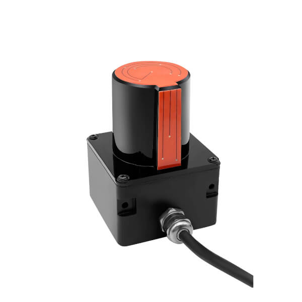
This article covers how CPJROBOT’s POELIDAR-F1 handles large-scale deployments — not the marketing version, but the practical side: how the cascade actually works, what it demands from your network and compute, and where it genuinely solves problems that other approaches do not.
Why a Single LiDAR Unit Is Not Enough for Immersive Spaces
A single POELIDAR-F1 covers a working radius of over 11 meters on a wall surface and over 13 meters on a floor. That is enough for a standalone interactive wall or a mid-sized floor projection. But immersive spaces are rarely simple rectangles.
Think about a 360-degree interactive room. A dome installation. An L-shaped corridor with projection on both surfaces. A trapezoidal floor combined with a curved rear wall. In each of these cases, a single LiDAR mounted at the center cannot cover the entire interaction zone without physical obstructions, angular dead zones, or accuracy degradation at the periphery.
Multi-sensor cascade solves this by assigning each LiDAR to a defined sub-zone, then merging all touch point data in real time at the software layer. The result is a unified interaction field — one system, one coordinate space, regardless of how many physical surfaces are involved.
How POELIDAR-F1 Cascade Works in Practice
The POELIDAR-F1 communicates over standard Ethernet with POE power delivery (IEEE 802.3af). This means every unit runs on a single CAT6 cable — power and data on the same line, no dedicated power supply per sensor, transmission range up to 100 meters from the switch.
From one computer, the CPJROBOT control software can manage 20 or more POELIDAR-F1 units simultaneously. Each unit sends its scan data to the central host, which registers each sensor’s physical position and orientation, then translates all incoming point clouds into a single unified coordinate system.
Zone configuration is flexible. Each LiDAR can be assigned a rectangular, circular, trapezoidal, polygonal, or freeform interaction area. Zones from multiple sensors can overlap, which is useful for covering shared transition areas between two display surfaces without leaving gaps.
Supported surface configurations include:
- Flat surfaces (standard walls, floor tiles, projection screens)
- L-shaped configurations (adjacent perpendicular walls)
- Tri-fold surfaces (three-panel setups for tradeshow booths or museum kiosks)
- Curved surfaces (arc screens, curved LED walls, dome segments)
Network and Compute Requirements
For most multi-LiDAR deployments, the compute and network requirements are modest. POELIDAR-F1 units generate relatively low data throughput — their scan output is a set of 2D point coordinates at up to 30 frames per second, not a video stream or full 3D point cloud. A standard gigabit managed switch is sufficient for networks of 10 to 20 units.
Key network considerations:
- Use a managed switch so you can assign each LiDAR to a VLAN or subnet and avoid broadcast collisions at scale.
- Keep individual cable runs under 90 meters to stay within CAT6 rated performance with POE headroom.
- For installations exceeding 20 units, split sensors across two managed switches connected via uplink.
On the compute side, a mid-tier workstation (Intel Core i7 / AMD Ryzen 7, 16 GB RAM) handles 20+ units with comfortable headroom. The bottleneck is rarely CPU — it is more often the responsiveness of the interactive content layer running on top.
Touch Output: Protocols and Integration
Once the cascade is running, the system outputs touch data through standard protocols:
- TUIO protocol — the standard for tangible user interfaces, supported natively by Processing, openFrameworks, and custom engines
- Windows multi-touch — native Windows touch input, up to 256 simultaneous touch points
- Mouse simulation — single-cursor fallback for simpler applications
For Unity developers, the CPJROBOT SDK provides a plugin layer that translates TUIO or Windows touch events into Unity Touch API calls. C# and C++ bindings are also available for custom engine integration.
Where This Works Well — and Where It Does Not
Strong fit:
- Permanent installations in museums, science centers, brand experience spaces, and commercial retail environments
- Large floor projections where camera-based tracking fails under overhead lighting variation
- Curved or non-planar surfaces that are physically difficult to instrument with other sensor types
- High-traffic public spaces where durability and maintenance simplicity matter
Less suitable:
- Outdoor daylight installations — direct sunlight can saturate TOF sensors
- Very small interaction zones (under 2 square meters) where a single camera or short-range IR sensor is simpler
- Temporary pop-up events where quick teardown matters more than precision
A Practical Starting Point
For integrators new to POELIDAR-F1 cascade deployments, CPJROBOT recommends starting with a two- or three-unit pilot on a representative surface type before scaling to a full installation. This surfaces any calibration quirks specific to your venue geometry and gives the content team time to validate touch precision against their UX targets.
CPJROBOT provides deployment documentation, SDK access, and technical support at [email protected].
CPJROBOT (Shanghai CPJRobot Co., Ltd.) specializes in professional interactive LiDAR systems designed specifically for the immersive installation and experiential space industry.